What is UML? UML (Unified Modeling Language) is a standardized way to visualize software system designs. Software developers and architects use UML diagrams — like class diagrams, sequence diagrams, use case diagrams, and activity diagrams — to communicate architecture, plan features, and document systems before writing code.
Where to create UML diagrams online? Sketchboard's UML diagram tool gives you a collaborative canvas to create all types of UML diagrams quickly. No setup required — just open your browser and start diagramming.
Use Sketchboard's online whiteboard to explore architecture ideas before refining them into UML, and review pricing when your team needs private workspaces, exports, and advanced sharing.
Create UML diagrams from anywhere at any time!
Rita from Boston
Saiki from Helsinki
sketchboard.me/aabbcc
sketchboard.me/aabbcc
UML Diagram maker for online collaboration
UML Diagram maker for online collaboration
Do you need a UML class diagram for software documentation, a UML use case diagram for mapping high-level requirements, or something else? Sketchboard’s UML Architecture diagram tool supports you to boost your team’s creativity and efficiency.
UML Diagram tool for software professionals
UML Diagram tool for software professionals
Sketchboard is designed for software engineering professionals by putting privacy and security to the core of its UML diagram software. Enjoy creating countless UML diagrams on Sketchboard’s infinite canvas securely.
Sketchboard is designed for software engineering professionals by putting privacy and security to the core of its UML diagram software. Enjoy creating countless UML diagrams on Sketchboard’s infinite canvas securely.
Share your UML diagram with ease
Share your UML diagram with ease
Online UML diagrams created on Sketchboard are easy to export as pdf, jpeg, png and svg. Slack, Google Drive and GitHub integrations make things even smoother for the software teams to develop class diagrams, sequence diagrams and all others.
Online UML tool for agile development
Online UML tool for agile development
Creating UML Architecture Diagrams is not always simple. Sketchboard’s real time collaboration features get your team a common understanding. Send and receive feedback with ease, increase the speed and quality of your software development process.
Creating UML Architecture Diagrams is not always simple. Sketchboard’s real time collaboration features get your team a common understanding. Send and receive feedback with ease, increase the speed and quality of your software development process.
Uses for UML Diagram Software
UML use case diagram tool
UML use case diagram tool
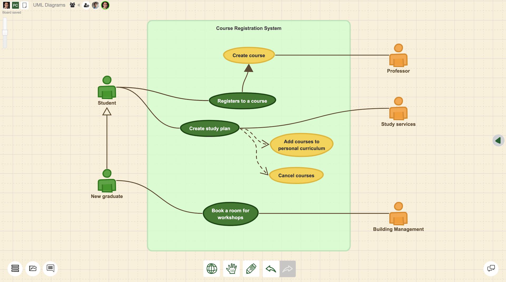
Use case diagrams allow you to draft out the services your system provides, giving you a chance to complete functionalities on a basic level before iterating your design further. Making a use case diagram with a UML diagram maker helps you to plan high level functionalities of your system.
Use case diagrams allow you to draft out the services your system provides, giving you a chance to complete functionalities on a basic level before iterating your design further. Making a use case diagram with a UML diagram maker helps you to plan high level functionalities of your system.
UML class diagram tool
UML class diagram tool
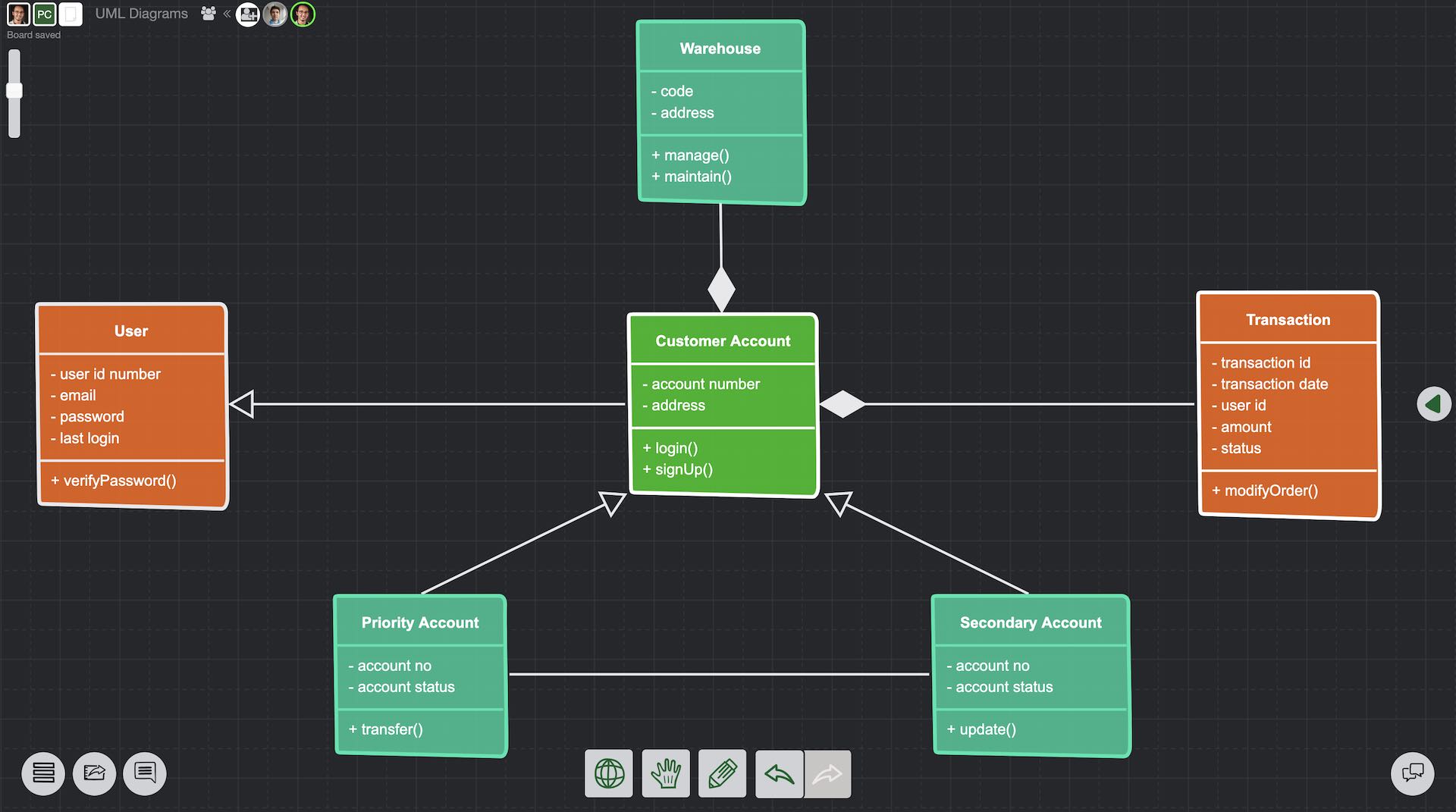
Class diagram is one of the structural UML types. Make a UML class diagram to give a notation baseline for other UML structure diagrams. UML class diagram tool helps you to demonstrate the structure of classifiers in the system. Class diagrams are also useful for business-focused teams in the organization.
Class diagram is one of the structural UML types. Make a UML class diagram to give a notation baseline for other UML structure diagrams. UML class diagram tool helps you to demonstrate the structure of classifiers in the system. Class diagrams are also useful for business-focused teams in the organization.
UML state machine diagram tool
UML state machine diagram tool
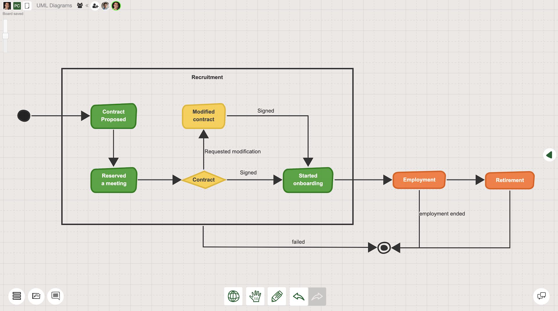
State machine diagrams (also known as state diagrams) are behavioral UML diagrams. Create UML State diagrams with Sketchboard’s online UML tool to document how an entity changes states as a response to different events. State diagrams are also useful to demonstrate the different use cases for business purposes.
State machine diagrams (also known as state diagrams) are behavioral UML diagrams. Create UML State diagrams with Sketchboard’s online UML tool to document how an entity changes states as a response to different events. State diagrams are also useful to demonstrate the different use cases for business purposes.
Why should I use a UML Diagram tool?
UML is widely accepted
UML (Unified modeling language) is one of the widest used process and workflow modeling languages. In addition to software architecture diagrams, UML diagrams can be used for other several business functions. Using a commonly accepted way to visualize your ideas can make things much easier.
UML diagram tool makes things smoother
UML Diagram makers support you to focus on the right thing: visualization your ideas. A good combination of flexibility and structure for a tool is a must. A UML Diagram designer shouldn't limit you, instead it should enhance your capabilities. Easy to use interface, infinite canvas, and rich icon library are important features to consider.
Being able to utilize a UML diagram tool will open up new possibilities in your team to visualize your ideas. Collaborative software diagramming tools sparks new ideas and makes difficult problems easy. Features such as comments and chat are worth checking out to get the best value from your online UML tool.
UML provides flexibility
UML offers a wide variety of structure and behaviour diagram options such as activity diagram, sequence diagram and deployment diagram. The uses of UML diagrams expanded into many other business and design related contexts. Using a UML Diagram tool can support you with various icons and structures that can be specialized in your domain.
UML diagrams: All you need to know
What is UML Diagram?
UML stands for Unified Modeling Language. It was developed during the 1990s to provide a standardized notation system for software development professionals. As UML gained popularity throughout the years, its usage has expanded into the fields of business, engineering, and design. In this article, we will primarily focus on software development use cases of UML diagrams.
The fundamental purpose of UML diagrams in software development is to map out components and processes of software systems. It is most often used for software modeling by software engineers and is one of the most widely accepted notation systems. Just like any other language, software development professionals can reduce misunderstandings across different teams by using a standardized way of visualizing software models.
Why should you use UML Diagrams?
As visualizing complex concepts often helps different stakeholders to understand and explain problems easier, UML diagrams play a very useful role in software development processes. As mentioned earlier, UML diagrams provide a standardized approach for visualizing complex software design elements.
Since there are various stakeholders involved in a software development project, it is crucial to have a common “language” that everybody is familiar with. Using a common notation helps every stakeholder to understand how components are structured and interact in a software system. As UML diagrams gain popularity across different fields, they almost became the default way to visually describe complex problems.
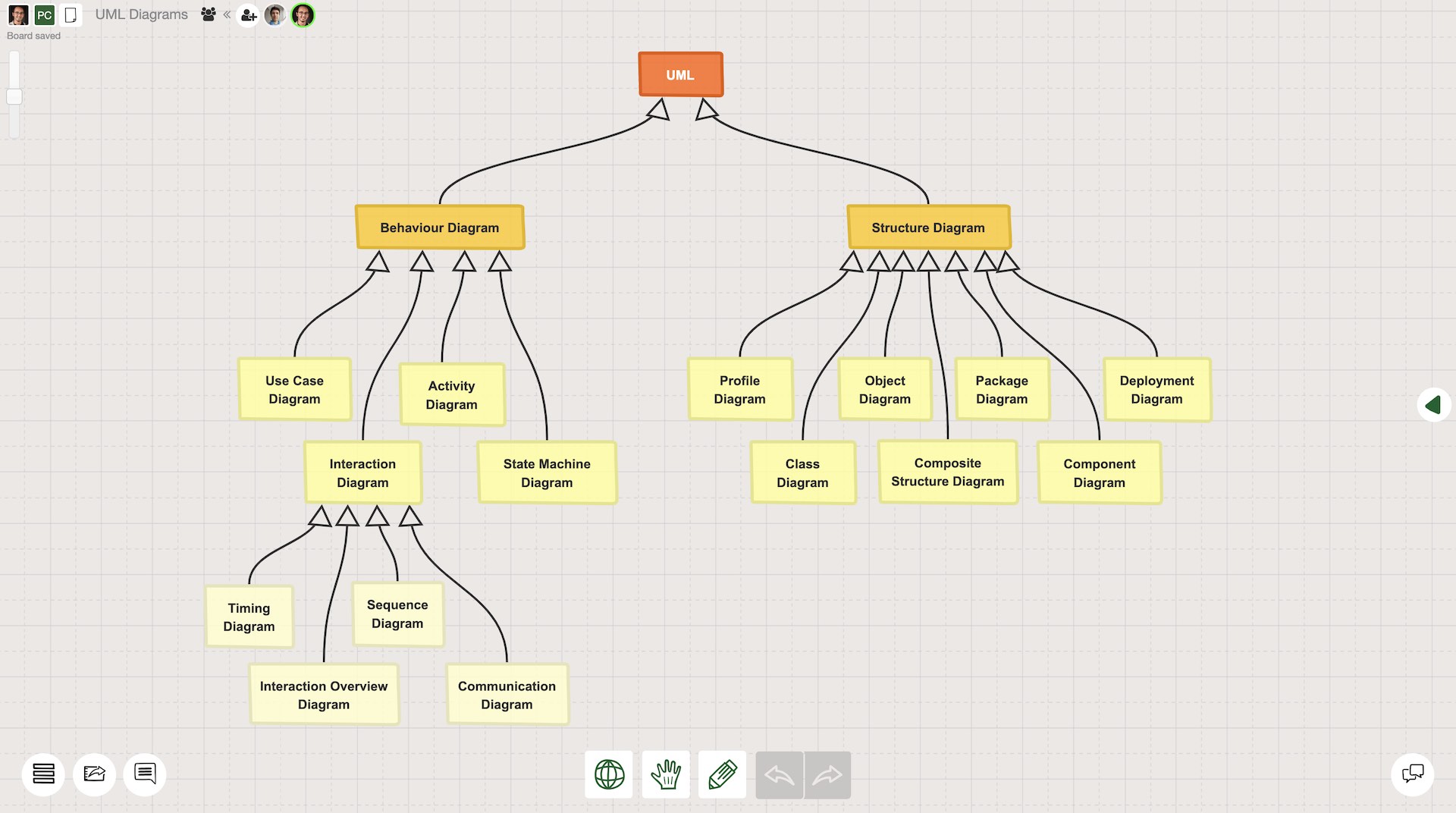
What are UML diagram types?
UML Diagrams are categorized into two types: structural diagrams and behavioral diagrams. Under each category, there are several diagram types. Check out a more comprehensive categorization of class diagrams below. In a nutshell, structural diagrams visualize how components are organized in a static format, while behavior diagrams describe the interactions between components in a more dynamic format. Sketchboard’s UML diagramming software is ready for the development teams with all the necessary features to model any kind of UML diagram with ease. Continue reading to learn more about the types of UML diagrams!
Structural diagrams
Structural diagrams explain how software system components are constructed by using various classes, attributes, and their relationships. Although there are many structural diagram types such as component diagrams, object diagrams, or deployment diagrams; the most commonly used structural diagrams are UML class diagrams. That’s why we will dig deeper into class diagrams first.
UML Class diagrams
Class diagrams demonstrate a static structure of a software system through class elements that are represented as rectangular and include information such as the class name, its attributes, operations, and behaviors.
A standard class component in a UML class diagram includes 3 parts:
The first section is the only mandatory section that includes the name of the class. It is the upper section represented in the class rectangle.
The middle section includes the attributes that the class has. For example, attributes of a user could be name, email, last login…
The last section contains the operations (also known as methods) which basically describe the interactions of the class with the data.
What does the ‘#’ symbol mean in a UML class diagram?
The visibility of each attribute and method can be specified by adding a character to the beginning. As each attribute can have a different access level, adding access level symbols can make the class diagram clearer.
‘+’ describes public attributes or methods
‘-’ describes private attributes or methods
‘#’ describes protected attributes or methods
‘~’ describes public attributes or methods
‘/’ describes derived attributes or methods
Class diagrams are very useful to conceptualize data structures in a software system. By illustrating classes and their relationships with each other, the software development team can have a clear understanding of the data model. Once the early version of the class diagram is created, the missing pieces in the structure become more clear. That can save a lot of time in a software development life cycle. A detailed illustration of the class diagram can make the implementation much easier and faster with fewer errors.
Other Structural UML diagrams
There are other types of structural UML diagrams actively used by professionals in various sectors. We briefly explained them below.
Profile diagrams are used for describing lightweight extensibility mechanisms to customize UML. Profile diagrams are generally used for creating a new metamodel for different platforms and domains, or for modifying and adopting an existing UML metamodel. Profile diagrams have three types of extensibility mechanisms: stereotypes, tagged values, and constraints.
Stereotypes represent how an object or element is extended as part of a profile. Using stereotypes allows you to create new elements with specific properties derived from existing ones.
Tagged values are used to extend the properties of an element to be able to include additional information.
Constraints depict -as the name suggests- limitations and conditions that occur continuously the same throughout the entire process.
UML Profile Diagrams are introduced in UML 2 in order to display these issues more clearly.
Object diagrams represent the structure of a modeled system by focusing on a particular set of objects and attributes at a specific time. Therefore they are also known as instant diagrams. As the object is defined as a specific instance of a class, a set of object diagrams can be created to test out the accuracy of a specific class diagram.
Compared to class diagrams, object diagrams are more concrete because they use real-world examples. Due to the similarities between two diagram types, the notation used for these diagrams are very similar to each other.
Package diagrams are used for explaining how elements are grouped in “packages” in a way that creates dependency relationships. Packages are defined as collections of logically relevant UML elements, and they are considered as file folders.
Package diagrams provide a clear picture of how distinct packages -and their elements- are organized in a hierarchical structure. These diagrams are used together with class and use case diagrams to provide further clarification to explain complexities by grouping classes into packages.
Deployment diagrams are another type of structural diagrams that are used to represent hardware and software components of a system such as web servers, application servers, database servers, web applications and databases. Deployment diagrams include information about how different physical elements and software on those elements are connected with each other.
Deployment diagrams are generally used when the software solution is required to be deployed to more than one machine. In addition to that, these diagrams are also useful for designing the architecture of a system.
Composite structure diagrams depict the relationship between the parts in a class. Entities that are used in composite structure diagrams are parts, ports, structured classifiers, connectors and collaborations. A composite structure can be defined as a set of interconnected elements working together for a common purpose.
Composite structure diagrams are detailed diagrams to explain the composition of an entity and internal actions of a class. As these diagrams provide insights on a micro level, they are useful for troubleshooting and more detailed planning.
Component diagrams display how physical and conceptual elements are connected with each other in a system. Historically, components diagrams have been used mostly for the physical aspect of a system. But together with UML 2, components started to be also conceptual. Component diagrams share a lot of similarities with class diagrams. Developers and system administrators use component diagrams for planning and assigning tasks. They provide a useful perspective about a component based system model.
Behavior diagrams
Behavior diagrams aim to demonstrate how the system is supposed to interact. These interactions could be between the system and its users, between different systems, or between the components of the same system. In a nutshell, behavior diagrams aim to emphasize the functionality of the system. There are several UML Behavior diagrams that are commonly used by software developers, architects, and analysts.
As describing interactions in a dynamic flow is quite challenging, visualization through UML diagrams makes a big difference for effective communication in software development teams. Therefore behavior diagrams such as use case diagrams, state diagrams, or sequence diagrams are widely used to speed up the work. There are seven types of behavioral UML diagrams. We will explain the most commonly used ones more in depth, and go through other ones briefly. Keep on reading!
Use case diagram
Mapping out fundamental functions of a system from users perspective is one of the fundamental steps of every software development project. Use case diagrams provide a clear framework for modeling how users interact with the system through functional requirements.
Use case diagrams are macro level diagrams that can be very helpful to create an overview of the system especially in the beginning of the software development process. Compared to many other UML diagram types, these diagrams are simpler with only three main elements:
Use case elements show functional requirements of the system in a simplistic form. These elements help development teams map out different ways that a user can engage with the system. These often include a verb to describe specific action to be taken by the user. In a more structured process, each use case element can be attached to a user story to provide further clarification.
Actors are the users of the system. They interact with the system based on a particular purpose to achieve. Actors can be people, organizations or another system/application.
Relationship: The association between use cases and actors are displayed through straight arrow lines.
When to use a use case diagram?
Use case diagrams are very effective for;
Mapping out users’ targets from a big picture perspective
Explaining interactions between the user and system to different stakeholders
Simplifying the workflow of the system by putting the users to the center
Demonstrating the high level requirements of a system in a larger context
State machine diagram
State machine diagrams (a.k.a.state diagrams) are used for explaining different states of an object in a system. These diagrams often demonstrate how an object can change its state under specific conditions or actions taken by the system or user. There are three main elements that are used in a state diagram.
State is defined as a situation of an object in response to the events that have an effect on the object during its lifetime in the system. It is represented in a rectangular shape. There are also special representations for the initial and final stateç
Transition is the path between different states displaying the logical flow of an object between different states. It is represented by the arrow lines.
Event is the specific trigger that makes an object change its state. It is represented by a text in the transition arrow line.
When to use a state diagram?
As one of the commonly used behavioral UML diagrams, state diagrams are very effective for;
Illustrating how a system work on a specific entity level
Explaining how an event-driven object can change its state in the system
Mapping out various use case scenarios to clarify potential flaws of the system
Clarifying all of the states and events that are attached to a specific entity in a system.
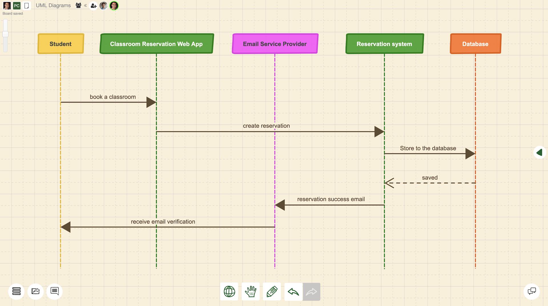
Sequence diagram
UML Sequence diagram (a.k.a. system sequence diagram) is a common type of behavioral diagram that demonstrates specifics of operations in a system. Compared to use case and state diagrams, sequence diagrams provide more information about the relationships between actors, and their actions with the system components. Horizontal axis represents various entities of the system which are involved in the workflow. These diagrams also provide information about the time dimension of the workflow through its vertical axis.
As sequence diagrams provide a more detailed view of the system also with the time dimension, there are several unique elements to be used. These elements are;
Actor is the user who interacts with the system’s defined workflow. As in many other UML diagrams, it is represented by a particular shape. In some of the diagrams, an actor can also be a non-human system component such as an external hardware or an application.
Lifeline depicts an element that is involved in the interaction. Lifeline is represented with a vertical dashed line to illustrate the time dimension.
Activation box defines a particular time period that an element is actively involved in an interaction. It is represented as a rectangle positioned on the relevant lifeline.
Message defines a particular relationship between lifelines. It can be represented as dashed or solid arrow lines.
When to use a sequence diagram?
Sequence diagrams are very effective for;
Explaining use case scenarios more in depth before coding starts
Providing clear guidance for the programmers
Modeling a complex operation, function or workflow
Demonstrating objects, components and actors' relationships in sequences.
Sequence diagrams are suggested to be used after use case diagrams to provide a more in depth understanding to the software development teams. As these diagrams give a dynamic view of a system, it can help programmers to clarify some abstract features and concepts before the coding process starts.
Other behavioral UML diagrams
There are four more structural UML diagram types that are briefly explained below. These diagrams are also very useful for programmers to speed up their development processes effectively.
Activity diagrams are used to demonstrate the workflows and processes with activity components. They are used for modeling both software and business processes. Activity diagrams show a flow of data, operation or any other kind of activity within a specified system.
Communication diagrams in UML explain interactions between objects. They include information about the system from sequence, class and use case diagrams. In theory, they present almost the same information with the sequence diagrams in a different structure. Compared to sequence diagrams, communication diagrams are more useful to explain the interactions between various elements without in depth time dimension. That makes it easier to focus on interactions rather than the particular sequence.
Interaction overview diagrams are considered similar to activity diagrams as they both represent activity sequences of the system. As the name suggests, these diagrams provide a high-level overview of the interactions where other type of UML diagrams can be combined as nested elements within these diagrams.
Timing diagrams are another type of UML behavioral diagrams that provide insight about interactions. These diagrams are primarily used to specify timing of the interactions across different entities of a system. Time dimension is represented on the horizontal axis and various entities such as values or states are represented on the vertical axis.
How to make a UML diagram?
As we mentioned above, UML diagrams provide a very wide variety of opportunities for software development teams to speed up their work. Depending on your needs, you can decide to use any type of UML diagrams for a start. In practice, all you need to create a functional diagram is a pen and a paper. With that said, online UML Diagramming Tools like Sketchboard can significantly improve your workflow and the efficiency of your team.
In this section, we prepared a UML Diagram Tutorial to provide some guidance on your journey so that you can get the best value out of your UML diagrams.
Step 0: Why do you need a UML Diagram?
First things first. Understanding your needs and goals to create a UML diagram is a very crucial step. As we explained in the previous sections, UML provides a wide variety of options to be used for different purposes.
After clarifying the purpose of the UML diagram, you can pick one or a set of UML diagram types you will use. It is important to get familiar with the fundamental elements, structure and notation of the diagrams. This is the part that Sketchboard can make a big positive difference with its UML diagram templates.
5 Step UML Diagram Tutorial
Step 1: Start with template or a blank page
After signing up on Sketchboard, you can decide to use a blank page to start or choose one of the templates that works for you. Sketchboard constantly enhances its template library to speed up software development teams.
Step 2: Put out the entities of the diagram
Once you have the canvas ready, start adding relevant components to the canvas. You can use the shape library on the right side, or context library by double clicking to the canvas and search for a particular shape. Depending on the type of your UML diagram, you should add actors, classes, lifelines, and more. Sketchboard’s flexible online whiteboard offers 400+ built in icons and shapes. If you cannot find what you are looking for, you can import images as well.
Step 3: Relationships
After most of the relevant entities add to the canvas, it is time to start defining relationships between those entities. Sketchboard offers an easy way to connect elements through lines that are organically arranged. If necessary, add explanations to the relationships, change the line and arrow formats to finalize the relationships.
Step 4: Rearrange and format the shapes according to your taste
Once all the elements and relationships are on the canvas, it is time to rearrange the shapes to create a clear picture. This is the step where you can also add colors or format line thickness as well.
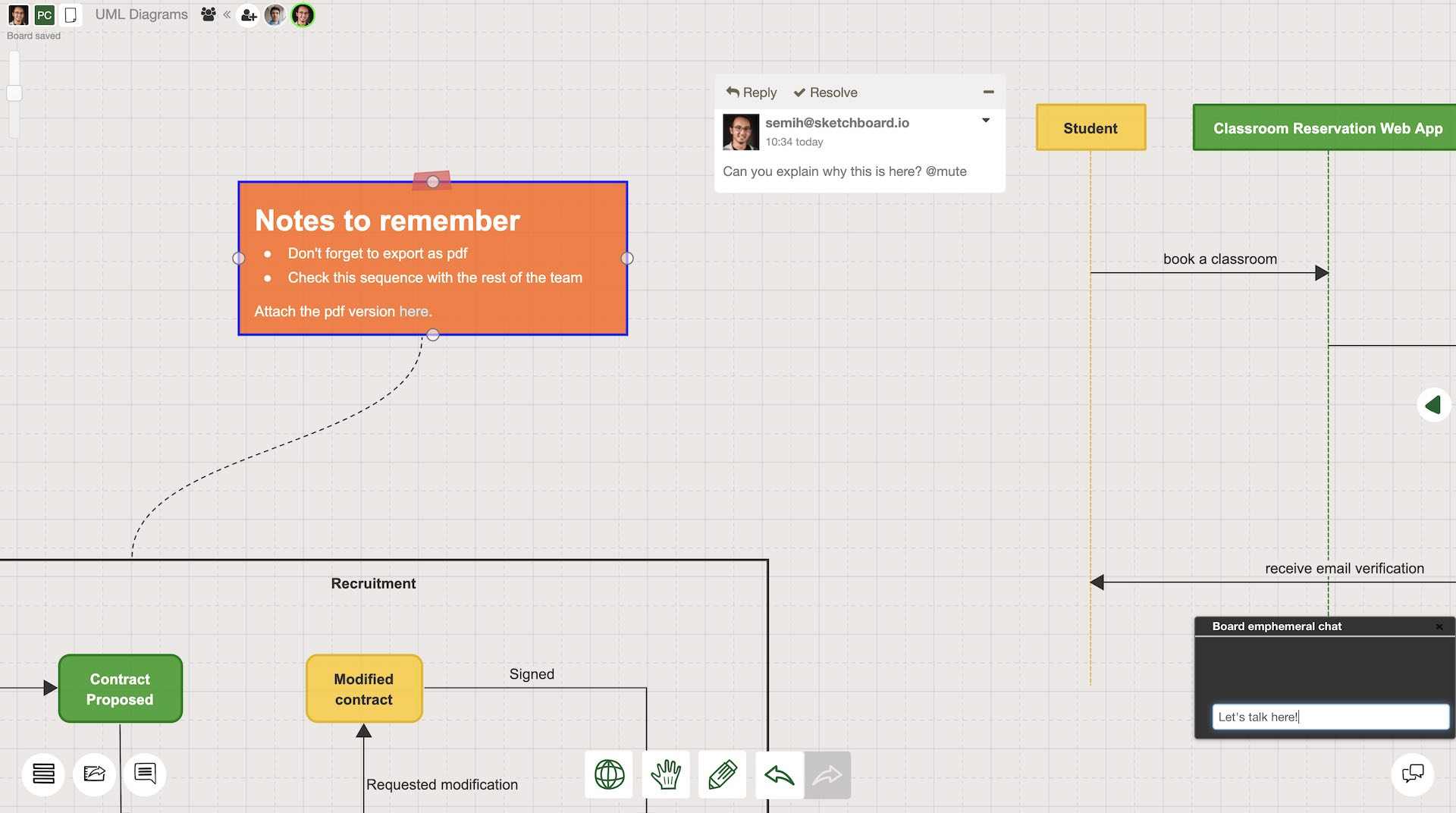
Step 5: Export, share and improve
Once you have the first version ready, it is time to share it with your colleagues to collect feedback for further improvement. Sketchboard real-time whiteboard helps your team to build diagrams together, collaborate through comments and notes on the canvas. Once it is time to share the diagram with others, you can publish it through integrations such as Google Drive, Slack, Microsoft Teams or Webex. You can also export selected elements or the whole canvas as pdf, svg, png or jpeg.
Feel free to contact us if you have any comments or suggestions to make your UML Diagramming journey even better. We are always happy to hear from you.
UML Diagram FAQ
What is UML?
UML (Unified Modeling Language) is a standardized visual language used by software developers and system architects to design, document, and communicate software systems. UML provides a set of diagram types — including class diagrams, sequence diagrams, use case diagrams, activity diagrams, and state diagrams — that help teams visualize system architecture, plan features, and document design decisions before writing code.
What are the different types of UML diagrams?
UML diagrams fall into two main categories. Structural diagrams show the static architecture of a system: class diagrams, object diagrams, component diagrams, deployment diagrams, package diagrams, and composite structure diagrams. Behavioral diagrams show how the system behaves: use case diagrams, sequence diagrams, activity diagrams, state machine diagrams, communication diagrams, and interaction overview diagrams. Most teams use class diagrams for architecture, sequence diagrams for workflows, and use case diagrams to capture requirements.
Where can I create UML diagrams online?
You can create UML diagrams online with Sketchboard's UML diagram tool — no installation required. Simply open your browser, start a new board, and use the UML shape library to drag-and-drop class diagrams, sequence diagrams, use case diagrams, and more. Collaborate in real time with your team, export diagrams as images, and integrate your UML designs with your development workflow. Sign up free to get started.
How do I create a UML diagram?
To create a UML diagram: 1) Identify which UML diagram type fits your need (class diagram for architecture, sequence diagram for interactions, use case diagram for requirements). 2) Open Sketchboard's UML diagram tool and select the relevant shape library. 3) Drag shapes onto the canvas and connect them with UML-standard relationships. 4) Add labels, multiplicities, and notes. 5) Share the board link with your team for real-time collaboration and feedback.